LORD Corporation
With more than 3,100 employees in 26 countries, 19 manufacturing facilities and 10 R&D centers worldwide, we're there for our customers.
Our Company
-
Products and Solutions
To speak to someone directly, call
Customer Support:
8AM–5PM EST
Technical Support:
8AM–5PM EST
-
Industries
To speak to someone directly, call
Customer Support:
8AM–5PM EST
Technical Support:
8AM–5PM EST
-
Our Company
To speak to someone directly, call
Customer Support:
8AM–5PM EST
Technical Support:
8AM–5PM EST
-
Feedback Button
Feedback Button
Questionnaire

Shock Isolation Theory
A special case of shock protection is found in the Shipping Container market. Here, the shock pulses are not defined as previously discussed but are specified in terms of being dropped from some height in a given configuration. Thus, the following discussion is presented.
The information here is presented to assist in the selection of LORD products to protect critical items in their shipping containers. It is intended that, for most applications, a mount from the line of standard LORD Shipping Container Mounts can be selected.
The basics of shock isolation are presented to give the reader an understanding of the effects of assumptions made during analysis of the system. The relationship of shock response to vibration response of the system as well as to the static stiffness characteristics of the mounts is discussed.
The variables which must be considered in the real world application of elastomeric shock mounts are presented. Included is a discussion of stiffness variation with strain and temperature and the effects of this variation on the overall response of the system.
Some basic equations are presented to allow calculation of system response in simple cases. For those instances where more elaborate analysis is required, a checklist of necessary information for a LORD analysis is provided.
Protect Your Valuable Cargo with Shipping Mounts
Theory
Although many factors can influence the dynamic response of a shipping container system, we may look at the overall problem as one of energy being imposed on the system. This energy must be stored, or dissipated. The energy stored in the mounts must then be released back to the system in a controlled manner such that the peak forces transmitted are below the critical level (fragility) for the mounted equipment.
With a given weight and geometry for the mounted equipment, the dynamic stiffness of the shock mounts is the adjustable factor at the designer’s disposal to provide the desired protection. This stiffness determines the mounted system natural frequency that, in turn, controls the rate at which the energy is returned to the system and the maximum forces which will be imposed on the equipment.
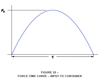
The energy input to the system enters over some time period (pulse length Ʈ) and reaches some maximum force level (Fo). Schematically, this would appear as shown in Figure 22 on a force-time curve. The area enclosed under this curve is proportional to the energy.
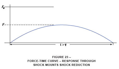
If the shock mounts are selected correctly to protect the mounted equipment, the response through the mounts will be such that the energy (assuming no dissipation) will be transmitted to the mounted mass over a longer time period than that at which it entered the mounts. With this longer time period, the peak force will be lower than that imposed at the outside of the container. This is shown in Figure 23. Here, the energy is the same as that from Figure 22.
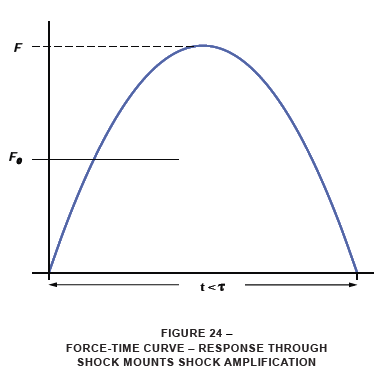
Conversely, if mounts are incorrectly selected, they could result in amplifying the peak forces seen by the mounted equipment. Figure 24 shows this case. Again, the energy is assumed equivalent to the original energy entering the container. It should be noted that the situation of Figure 24 (shock amplification) can occur in a number of ways. Among these are:
• Incorrect mount stiffness
• Non-linear mount stiffness in the necessary deflection range
• Insufficient sway space available within the shipping container
Thus, it is important to accurately define system parameters, select appropriate shock mounts and design the shipping container with the mounting system in mind.
Basic Shock Equations — The basic equations for initial estimates of shock isolation systems are fairly simple. They involve the input to the system and the characteristics of the mounted mass and the shock mounts. In general, the shock to the system is modeled as an instantaneous velocity change for most shipping container applications.
We start the analysis knowing the impact velocity of the container into the barrier or floor. Typically, the velocity for a side or end impact is specified. For drop tests, this velocity must be calculated.
For a straight, vertical drop:

Where:
Vo = impact velocity (in/sec)
g = acceleration due to gravity (386 in/sec2)
h = drop height (in)
The next necessary item to know is the system natural frequency:

Where:
fn = system natural frequency (Hz)
K' = system dynamic spring rate (lb/in)
W = supported weight (lb)
Then the response acceleration may be calculated:

Where:
Ao = response acceleration (g)
Vo = impact velocity (in/sec)
fn = system natural frequency (Hz)
as well as the deflection across the shock mounts:

Where:
d = system deflection (inches)
Ao = response acceleration (g)
fn = system natural frequency (Hz)
Of course, equation (3) may be solved in reverse if the equipment fragility is known and the system natural frequency is required.

From this, we calculate the dynamic stiffness (spring rate) of the shock mounts required to provide the desired protection.

Where:
K' = dynamic stiffness of mount(s) (lb/in)
fn = system natural frequency (Hz)
W = supported weight (lb)
The above is the basic analysis conducted for the less involved shipping container applications. It is based on several assumptions:
• The support structure is infinitely rigid.
• There is no rebound of the container from the impact surface.
• There is no damping in the system.
• The mounted unit does not rotate.
• Shock mount stiffnesses are linear in the working range of deflection.
These same assumptions are carried through the remainder of this discussion. The first three tend in the direction of making the analysis conservative. The last assumption is one which must be watched closely based on mount size, shock levels and installation geometry.
Shipping Container Mount Descriptions
The great majority of elastomeric (rubber) shipping container mounts are of a “sandwich” type construction. That is, there are typically two flat plates, with threaded fasteners installed, which are bonded on either side of an elastomeric pad. The general construction is shown in Figure 25.
The shape of the mount can vary depending on the needs of a particular application. The standard product lines for LORD shipping container mounts are shown in the product section.
Shipping Container Mount Stiffness
As was shown in the previous section, the stiffness of the shipping container mount determines the dynamic response of the support system. This mount stiffness depends on the geometry of the mount and the properties of the elastomer. The general equation for the shear stiffness of an elastomeric sandwich mount is:

Where:
KS = shear stiffness (lb/in)
A = elastomer cross-sectional area (in2)
G = elastomer shear modulus (psi)
tR = elastomer thickness (in)
The compression stiffness of a sandwich mount is higher than the shear stiffness by some value. This ratio of compression to shear stiffness is known as the “L” value for the mount, or:

Where:
KC = mount compression stiffness (lb/in)
KS = mount shear stiffness (lb/in)
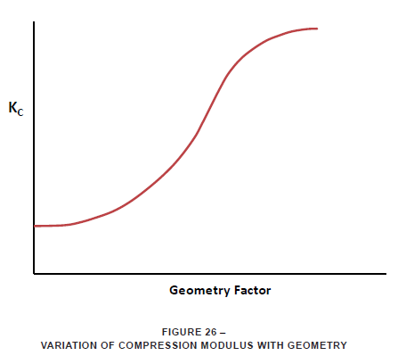
The compression stiffness, like the shear stiffness, is dependent on geometry and elastomer properties. Here, the elastomer property of concern is the compression modulus. The complicating factor is that the compression modulus varies, in a nonlinear fashion, with the geometry of the mount. Figure 26 shows the general trend of the variation of compression modulus versus a geometry factor. The shape of this curve also varies with the basic hardness of the elastomer compound being used.
It is not the intent of this page to present mount design, but only application. Thus, let it suffice to say that, with the above background, there are specific ratios of compression to shear stiffness for various geometries for the mounts used in the shipping container industry. The “L” value is important to calculations of dynamic performance of a shipping container suspension.
The general relationship of the stiffness of the mounts, in various directions of loading, is shown schematically in the load versus deflection graph of Figure 27. It is important to note the range of linearity of the various curves. In shear, sandwich mounts can be linear up to deflections equal to 2.5 or 3.0 times the rubber thickness. In compression, this linear region may be only up to 0.25 times the rubber wall length. Shipping container mount systems assume linear stiffnesses of the mounts. Thus, care must be observed in interpreting results, particularly when compression loading of the mounts occurs.
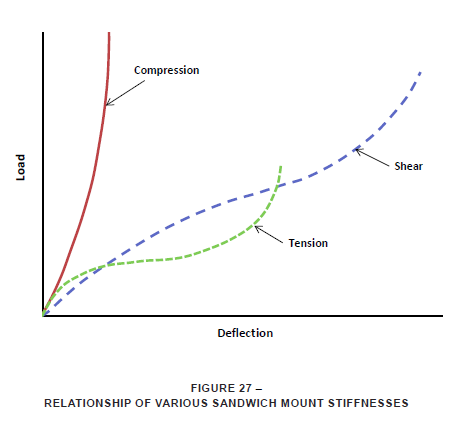
NOTE: Mounting systems are not designed to load mounts in tension. Tension loading is to be avoided as much as possible.
In general, the best protection from shock is provided by using the mounts in a shear mode. This is not always practical nor possible as will be shown in the next section.
System Installations
Depending on system requirements, shock mounts may be installed in shipping containers in a variety of configurations. Each type of installation has a distinct response characteristic. A key concept for analyzing any shipping container mounting system is that of “elastic center.”
The elastic center of a mounting system is that point in space about which the mounted equipment will rotate when subjected to an inertial load (acting through the center of gravity). The location of the elastic center of a mounting system depends on the orientation and spring rate characteristics of the mounts in the system. In most shipping container installations, the sandwich type mounts are used. This type of mount tends to project the elastic center approximately on a line extended from the compression axis. The actual point of projection depends on the “L” value of the mount being considered.
This may be demonstrated best by looking at some typical shipping container mount installations.
Simple Shear System
The simple shear system is the easiest to analyze and understand. It has some advantages to the container manufacturer in simplicity of installation, but also has some disadvantages in performance, centering on the compression stiffness characteristics of the isolator.
>The simple shear installation of shock mounts is shown in Figure 28.
Where:
E.C. = Elastic Center of Mounting System
C.G. = Center of Gravity of Mounted Equipment
In this system, the shock mounts react loads, in the vertical and fore-aft directions, through shearing of the elastomer. This is the softest direction of the mounts and will result in the lowest accelerations transmitted to the supported equipment. Loading in the lateral direction is absorbed in compression of the mounts and rotation about the elastic center (E.C.) of the system, as shown schematically in Figure 29. This type of response is typical of side impact tests. The rotation is the result of the inertial force imposed at the center of gravity (in a shock situation) which causes an overturning moment around the system elastic center.
Focalized Systems
In some container installations, the simple shear system results in unacceptably high transmitted shock loads in the lateral direction or in unacceptably high rotational deflections at the outer edges of the mounted equipment. In such cases, “focalized” systems are often used.
The shock mounts in such systems are “focused” at some angle such that the offset between the elastic center and the center-of-gravity is reduced. This reduced offset lessens the overturning moments due to side impacts and, thus, results in less rotation of the mounted equipment. The compromise with a focalized system is that the mounts are not being loaded in shear; neither in the vertical direction for a semi-focalized system, nor in any axis for a fully focalized system. This situation leads to a combination of shear and compression loading which will result in a higher effective mount stiffness and higher ‘g’ loads in directions that were previously shear axes. Conversely, directions that were previously compression will have a lower stiffness and will result in lower ‘g’ loads.
Figures 30 and 31 show semi-focalized and fully focalized systems, respectively. The semi-focalized installation has the mounts angled upward from the horizontal plane. This raises the elastic center of the mount system, increases the vertical system stiffness (due to the combination of compression and shear loading), but keeps the fore-aft axis completely in shear. The fully-focalized system places the mounts at angles up from the horizontal plane and inward toward the center of the mounted equipment. This arrangement results in combined shear and compression loading in all directions.
Low Fragility
Some types of equipment are more fragile than others and require better protection in their shipping containers. If the required protection cannot be achieved through the use of any of the previously described mount systems, then something special must be done. There are two basic options. First, standard sandwich mounts may be used in a gimballed arrangement. Second, a special mount design may be conceived to provide low spring rates and high deflections in all directions.
The gimballed system is shown in Figure 32. This system will use more mounts and will require considerable space for mounts, but it does have the advantage of using available mount geometries. The special design option will be more compact but has the disadvantages of development time and lack of availability.
CAUTION: When analyzing low fragility systems, special consideration must be given to the system natural frequency. The system natural frequency must always be calculated and checked against various system requirements. One concern with low fragility systems is that they typically require very low natural frequencies and could fall into critical vibration frequency ranges for various methods of transportation (3 to 7 Hz). Thus, a low fragility mounting system may provide excellent shock protection but it will require significant sway space and could cause system natural frequencies to fall into critical ranges. Another concern here is the large static deflection imposed on the mounts. This can, over long periods, degrade performance. In cases where a low frequency system is indicated, the designer is encouraged to contact LORD.
Proporties of Elastomers
The “spring” portion of typical shipping container mountings is an elastomer (rubber) specially compounded and processed to provide certain stiffness characteristics. The standard line of LORD shipping container mountings uses a specially compounded synthetic elastomer which is called SPE® I. This material has high strength, medium damping and good low temperature flexibility – all of which are important to shipping container use.
Besides SPE I, other elastomers can be used but are less suited to the job at hand. For example, natural rubber has excellent strength but is not a good candidate where very low temperature performance or damping is required. Neoprene, another elastomer which has been used in some past shipping containers, is not recommended for low temperature applications.
A brief discussion of some of the properties of SPE I elastomer will give background in the behavior of elastomeric shock mountings.
Stiffness Versus Temperature
Figure 33 shows the trends of elastomer stiffness versus temperature for typical SPE I elastomer, Natural Rubber and Neoprene compounds. The data on which these curves are based was compiled using low amplitude motions across standard samples of the various elastomers. It is immediately obvious that the SPE I elastomer material is far superior to typical ranges of operation for shipping containers. This is the basic reason that LORD standardized on the SPE I elastomer for shipping container mounts.
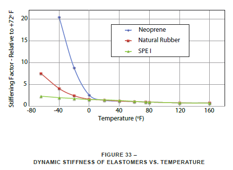
Even more important is the fact that the variations in stiffness with temperature, as shown in Figure 33, must be taken into account when analyzing a shipping container installation. At low temperatures, the system natural frequencies and transmitted accelerations will be higher than at room temperature. At high temperatures, the natural frequencies and transmitted accelerations will be lower than at room temperature – provided there is enough space in the container for the system to deflect without bottoming.
Stiffness Versus Strain
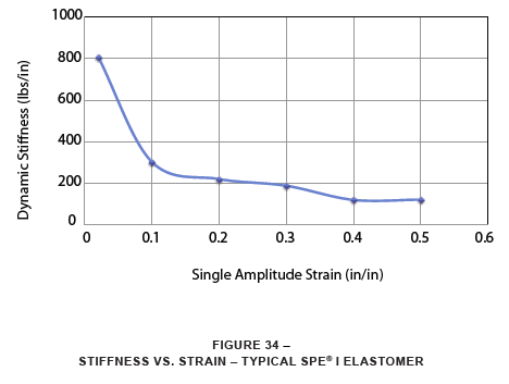
Along with variations in stiffness with temperature, elastomers also exhibit different stiffnesses at different strain levels. At low strain levels, elastomers are stiffer than at high strain levels. Strain is defined as the deflection across the elastomer divided by the thickness of the elastomer.
The reason for this “strain sensitivity” of elastomers lies in the molecular structure of the material. Typically, the more complex the molecular structure, the higher the damping in the compound, the more pronounced the strain sensitivity will be.
The importance of this subject to the analysis of a shipping container suspension is that it must be recognized that an elastomeric shipping container mount will exhibit different stiffnesses when tested under different conditions. In general, under shock an elastomeric mount will be stiffer than when it is tested statically (with a slowly applied load). Further, an elastomeric mount will generally be stiffer still under most vibration tests than it is under shock conditions. As a rule of thumb, then it should be remembered that:

Figure 34 shows the change in stiffness of a typical SPE I elastomer versus strain. Such a curve may be used to roughly estimate shock mount stiffness when the dynamic conditions imposed on the mounts are known.
Drift
Elastomeric mounts under load will drift and increase their static deflection with time. This characteristic must be understood and taken into account when planning the amount of necessary sway space in a shipping container.
The total deflection to be planned for must include static deflection, dynamic motion and drift. This latter item will depend on the amount of load on the mount, the direction of the load and the temperature at which the mount is being loaded.
Due to the nature of the variables involved, it is difficult to generalize as to the drift characteristic. Some data is available which can be used as a guideline. A typical curve is shown in Figure 35.
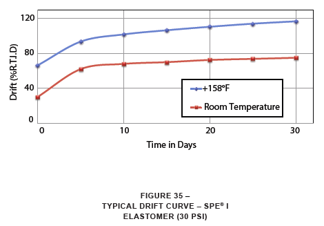
Figure 35 shows room temperature and elevated temperature +158°F (+70°C) drift curves for a medium stiffness SPE I elastomer sample loaded at a static stress level of 30 psi. The shape of the curve is typical of elastomeric drift. The greatest percentage of drift occurs within the first 2 to 3 days after the load is applied. After that, the rate of drift slows asymptotically. Thus, some estimate of total drift can usually be made and included in calculations of necessary sway space. The vertical axis of Figure 35 is in “Percent of Room Temperature Initial Deflection.” Thus, for example, if a system deflects 1.0 inch under its initial load at room temperature, it may be expected to deflect another 0.80 inch (approximately) after one month at room temperature, under a constant static load. This extra deflection must be allowed for in the internal sizing of the shipping container.
System Analysis
The following section gives a basic method for analyzing the simplest shipping container shock conditions. The following is based on several assumptions which must be kept in mind:
- The properties of the shock mounts are assumed to be linear.
- The container and mounted unit are inelastic (infinitely rigid).
- The velocity change of the moving container is instantaneous upon impact.
- All kinetic energy is stored in the mounts – no energy is dissipated.
- The system is uncoupled in all directions for flat bottom and edgewise drops.
- For a flat side drop, the effects of phase relationship between translational and rotational modes are neglected. They are assumed in phase, which covers the worst case.
As a rule of thumb for these simplified analyses, the effects of coupling are considered minimal if the eccentricity (e) of the center-of-gravity from the elastic center is one third, or less, of the shortest distance between mounts. This applies providing the unit is nearly symmetrical and homogeneous.
Refer to Symbols section for list of symbols as used in the following analyses.


This energy must be stored in the mounts.

Where:
K'V ≈ KV for natural rubber and neoprene
K'V ≈ 1.3 KV for SPE I elastomer
Note: These relationships are valid when strains are approximately 100% or greater.
- Calculate the maximum deflection required:
- Calculate the drop energy:
- Calculate the system dynamic vertical spring rate:
Coupled Flat Side Drop Analysis


Note: Using d/2 gives approximation of C.G. deflection of coupled system. This energy must be stored in the mounts.

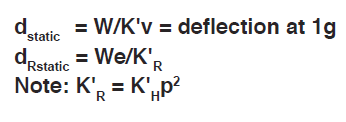
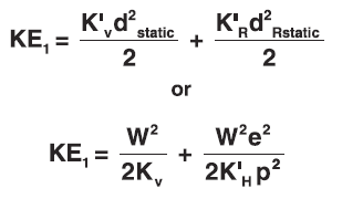


- Calculate deflection required for linear uncoupled system:
- Calculate drop energy:
- Calculate translational and static rotational deflection:
- Total energy equation is: (1g condition)
- Total acceleration at C.G. is approximately:
- G load calculated is for C.G. location only since moment equals weight times eccentricity (e) in the solution. Loads at points closer to E.C. than C.G. will be greater than G.
- Calculate deflection:
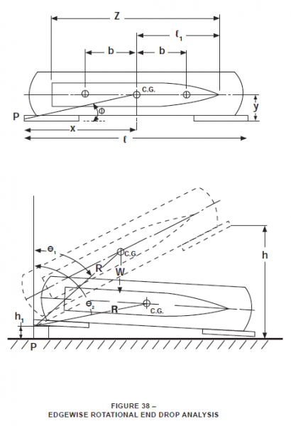
Edgewise Rotational End Drop Analysis
A) General System Parameters

Where:
R = distance from pivot point to C.G.
x = horizontal distance from pivot point to C.G.
y = vertical distance from pivot point to C.G.

Where:
IP = pitch moment of inertia (in-lb-sec2)
ICG = mass moment of inertia about C.G. (in-lb-sec2)
M = mass of suspended unit (lb-sec2/in)

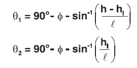
Where:
θ1 = angle between a line joining C.G. and pivot point (P) and vertical before drop
θ2 = angle between a line joining C.G. and pivot point (P) and vertical after drop
ϕ = tan-1(y/x)
h = drop height (inches)
h1 = vertical distance of pivot point above floor (inches)
ℓ = length of container, overall (inches)

Where:
ω0= angular velocity at impact (rad/sec)
g = acceleration due to gravity (386 in/sec2)

Where:
V = normal linear velocity of C.G. at impact (in/sec)

Where:
V1 = normal linear velocity of unit end due to rotation about C.G. (in/sec)
ℓ1 = distance from C.G. to end of unit (inches)
- Calculate:
- Pitch moment about point P:
- Radius of gyration about point P:
- Angles of Figure 38:
- Angular velocity at impact:
- Linear velocity of C.G. normal to container base at impact (t=0):
- Linear velocity of unit end due to rotation about C.G., normal to container base at impact:
- To continue with analysis, the maximum vertical acceleration at C.G. of unit (B1) and the maximum vertical acceleration at end of unit due to its rotation about C.G. (B2) must be estimated based on the number of “G’s” a unit can safely take (GT).
Generally, a scalar sum of B1 + B2 is made equal to GT. Then B1 + B2 = 386 GT
For softer systems, i.e., GT = 10 or less G’s, it is desirable to maintain a ratio of B1 / B2 = 1 or B1 = B2
Therefore, B1 = 386 GT / 2 and B2 = 386 GT / 2
B) System Response in Translation at Moment of Impact


- Vertical translational circular frequency:
- Vertical dynamic spring rate:
C) System Response in Rotation


- Rotational circular frequency about C.G.:
- Rotational dynamic spring rate:
- Mounting spacing:
D) Total System Response
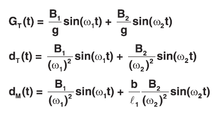
Note: If ω1 and ω2 are very close together then sin(ω1t) and sin(ω2t) will approach 1 at the same time t giving:
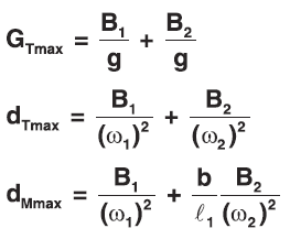
At this point overall balance and practical design of the system must be considered.
• Relationship of b to z and ℓ1
• Comparison of ω1 and ω2 and B1 and B2 (well balanced system has ω1 ≈ ω2 and B1 ≈ B2 if possible)
E) Mounting Calculations

Where:
n = number of equally loaded mounts

Note: a) and b) are valid for strain values of 100% or greater.
- Mounting dynamic vertical spring rate:
- Mounting static vertical spring rate:
- Mounting is selected on the following basis:
- Static spring rate
- Deflection capability (linearity and strain)
- Shear area (stress)
- Fatigue
- Material (special properties, i.e., temperature, etc.)
F) Container Clearance
- Total clearance is found by considering dynamic deflection, permanent set and safety factor


- Total clearance for SPE I elastomer mountings
- Total clearance for rubber or neoprene
Note: For temperature sensitive elastomer, total clearance should be based on high temperature performance.
Combination and Oblique Drops
Cornerwise Rotational End Drop
Analyze same as edgewise rotational end drop.
Cornerwise Drop
Calculate same as flat drop. Be certain to avoid “pure” compression loading on mounts. Offset mounts from plane through C.G. and corner to induce rotation upon impact.
Incline Impact or Pendulum Impact
Analyze as flat side drop using drop height equal to vertical rise of C.G. about point of impact. The following formula may be used.

Tip Over - Roll Over
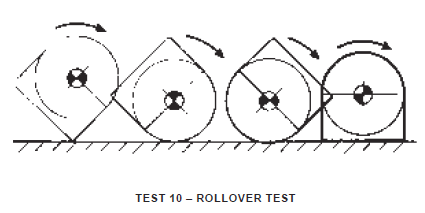
Analyze as edgewise rotational drop for side to bottom or side to top and as equivalent flat side drop for bottom to side or top to side. (Cylindrical containers should be designed to include roll-over flanges – no analysis is applicable.)
Coupled Systems
When the elastic center and center of gravity of a mounted system do not coincide, the system will, under dynamic excitation, exhibit combinations of translational and rotational modes. There are two ways of looking at this situation.
First, the system can be used as is and the rotational natural frequency calculated to determine if there is any reason for concern related to the dynamic environment to be encountered. Second, if it is determined that coupling, rotation, of the system cannot be tolerated, then the focalization angles for the mounts may be calculated to reduce or eliminate rocking of the mounted unit. The analyses of both of these cases depend on the geometry of the mounted system and the characteristics of the mounts.
The following calculations are for the above cases. Results in two coupled natural frequencies (fc):
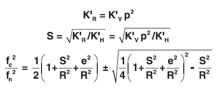
Note: For fore and aft input, use b (1/2 mount spread, Figure 38) in place of p, fore and aft spring rate in place of KH, and pitch radius of gyration.
L value – Ratio of Compression to Shear Spring Rate:
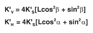
Note: Above analysis assumes system uses four mounts.
Vibration Testing
The preceding analyses have been focused on shock (drop) testing of shipping containers. Most shipping containers must also be exposed to some vibration testing and a review of critical frequencies should be made.
The key here is to recognize that the stiffness of an elastomeric isolator will typically be higher during vibration testing than during a shock or static test. The amount of stiffening depends on the magnitude of the vibration, which translates into strain across the elastomer.
The strain, during a vibration test may be calculated roughly as:

Where:
ε = strain (in/in)
Xi = double amplitude input vibration level (in)
TR = resonant transmissibility (assume 5 for SPE® I elastomer)
tR = thickness of elastomer (in)
Once the dynamic strain is calculated, Figure 34 may be used to estimate the dynamic stiffness versus the static stiffness of the mount. Then, the system natural frequencies may be calculated using the analysis previously presented.
If a resonant dwell vibration test is to be conducted, it is normal to run the test intermittently to avoid overheating the elastomeric mounts due to hysteretic heating. The surface temperature of the mount should not be allowed to exceed +115°F (+46°C).
Mount Selection
Once the dynamic analyses are completed and the required mount stiffness is known, the appropriate mount may be selected. This selection will be based on stiffness, maximum stress and maximum strain. The following guidelines are applicable to LORD SPE I elastomer shock mounts:
- Maximum dynamic stress should be limited to 225 psi or less. The analysis of the most severe shock at the lowest operational temperature will result in the highest dynamic load.
- Maximum static 1g stress should be limited to 25 psi or less.
- Maximum dynamic strain should be 250%. The analysis of the most severe shock at the highest operational temperature will result in the highest dynamic strain.
Standard Mounts
The product section contains the standard sizes of shipping container mounts manufactured by LORD using SPE I elastomer. Wherever possible, these mounts should be used. They were selected based on years of usage data for many shipping container applications.
Standard Shipping Container Shock Tests
No matter what mode of transportation is used, shock represents the most serious threat to equipment reliability. The standard tests described here are intended to simulate the worst shock conditions that would be expected for shipping/handling environments. Selected tests from those shown here are included in packaging specifications and used for designing shipping container suspension systems.
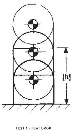
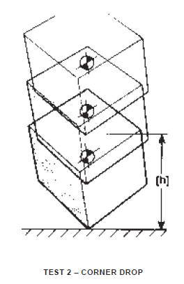
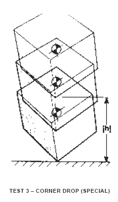
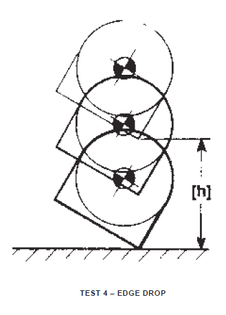
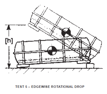
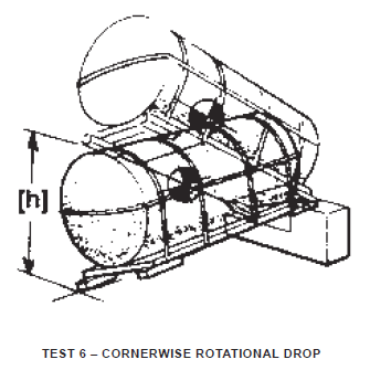
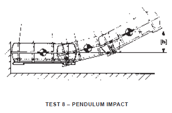
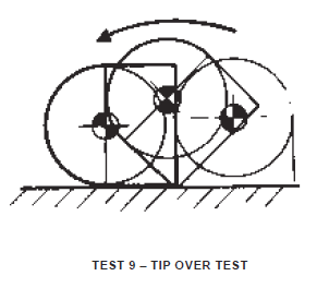
The letter “h” in the diagrams depicts the drop height specified in the applicable packaging specification. Exceptions: in Test 7 and 11 an impact velocity will be specified; in Test 9 and 10 neither drop height nor velocity is specified.
Flat Drop – Test 1
Container shall be raised the specified vertical distance and allowed to fall freely to a concrete or similarly hard surface so that container strikes flat on the skids or surface involved.
Corner Drop – Test 2
Container shall be raised the specified vertical distance such that the container is suspended with the center-of-gravity vertically above the striking corner. Container shall be allowed to fall freely to a concrete or similarly hard surface, striking corner first. Cylindrical containers shall be dropped on each quarter or corner.
Corner Drop (Special) – Test 3
Container shall be raised the specified vertical distance so that it will strike at the greatest angle possible, still ensuring that the container will come to rest on its base. The test shall be repeated for each of the corners or quarters.
Edge Drop – Test 4
Container shall be raised the specified vertical distance, such that the container is suspended with the center-of-gravity vertically above the striking edge. The container shall be allowed to fall freely to a concrete or similarly hard surface, striking edge first.
Edgewise Rotational Drop – Test 5
Container shall be supported at one end of the base on a sill or block of specified height and at right angles to skids. The opposite end shall be raised to the specified vertical height and allowed to fall freely onto a concrete or similarly hard surface. If container size and center-of-gravity location prevent dropping from prescribed height, the greatest attainable height shall be the height of the drops.
Cornerwise Rotational Drop – Test 6
Container shall be supported at one corner of its base on a low sill or block of specified height. The other corner of the same end shall be supported by a higher sill or block. The lowest point of the opposite end shall be raised to the specified vertical height and allowed to fall freely onto a concrete or similarly hard surface. If container size and center-of-gravity location prevent dropping from prescribed height, the greatest attainable height shall be the height of the drops.
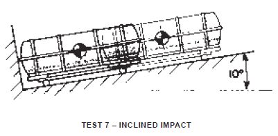
Inclined Impact – Test 7
Test shall be in accordance with ASTM Standard Method D880, “The Inclined Impact Test for Shipping Containers,” suitably modified to accommodate the container. Velocity at impact shall be as specified. The Pendulum Impact may be used in lieu of this test, and vice versa.
Pendulum Impact – Test 8
Container shall be suspended by four or more ropes or cables 16 feet or more long. Container shall be pulled back so that the center-of-gravity has been raised the specified distance. Container shall be released, allowing the end surface or skid, whichever extends further, to strike on an unyielding barrier of concrete or similarly hard material that is perpendicular to the container at impact.
Tip Over Test – Test 9
Container, erect on its base, shall be slowly tipped (in the direction specified) until it falls freely and solely by its own weight to a concrete or similarly hard floor.
Rollover Test – Test 10
Container, erect on its base, shall be tipped sideways until it falls freely and solely of its own weight to a concrete or similarly hard surface. This shall be repeated with falls from the side to top, from top to the other side, and from other side to the base, thus completing one revolution.
Rolling Impact Test (Cylindrical Containers) – Test 11
Container shall be allowed to roll down an incline on its rolling flanges and shall strike a vertical, rigid, flat surface at a specified velocity.

